


 122 / 308

122
toll free 800.307.6702 MASTERVOLT | mastervolt.com MARINCO | marinco.com ANCOR | ancorproducts.com
Manage:
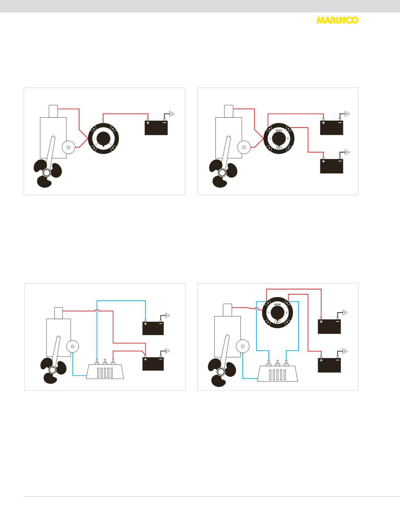
Wiring System Diagrams
As more and more electronics and electrical accessories are added to your boat (autopilot, refrigeration, etc.) the use of
multi-batteries becomes a necessity. Guest components allow you to set up the system (from simple to complex) for your
boat’s application. The following diagrams are for use in identifiying and designing the right system for your boating needs.
Detailed installation schematics are available. Request Guest form I-21681.
Single battery
Installation: To shut off all power at source. Recommended
installation by approved authorities.
Two battery with out isolator
Installation: To select a starter battery and ship service battery.
Manually isolates each battery, parallels both batteries for
emergency start, master disconnect, manually selects batteries
for charging.
12VOLT
BATTERY
ALT
STARTER
ON/OFF
SWITCH
ENGINE
1
12VOLT
BATTERY
12VOLT
BATTERY
ALT
STARTER
BATTERY
SELECTOR
SWITCH
ENGINE
1
2
2
1
Two battery with isolator
Installation: Isolator automatically selects lower charged battery
to be charged first. Full battery can't discharge to drained
battery. Dedicated system, no flexibility, no emergency parallel
or disconnect function.
Two battery with emergency parallel
Installation: An isolator automatically isolates each battery,
lower charged battery will automatically be charged first. Two
different size batteries can be used, larger for ship services,
smaller for engine cranking. Switch selects usage, master
disconnect, emergency parallel function.
12VOLT
BATTERY
12VOLT
BATTERY
ALT
STARTER
ENGINE
ISOLATOR
1
2
2
1
12VOLT
BATTERY
12VOLT
BATTERY
ALT
STARTER
BATTERY
SELECTOR
SWITCH
ENGINE
ISOLATOR
1
1
2
2
2
1